Directional line source
Prepared on the basis of the results of research task No. II-41 carried out in 2021-2023 entitled "Research on acoustic field control on the example of a matrix sound source with controlled directional characteristics" financed by the Ministry of Education and Science from a subsidy for the maintenance and development of teaching and research potential.
The directional line source was developed according to the dimensions shown in Fig. 1. The source is 380 mm wide, 100 mm high and 65 mm deep. The 60 mm wide loudspeakers are arranged in such a way that a distance of 20 mm separates them from the edge of the source, and a free space of 10 mm is left between the loudspeakers. When designing the housing, the rule was to make it as narrow as possible to avoid spatial aliasing.
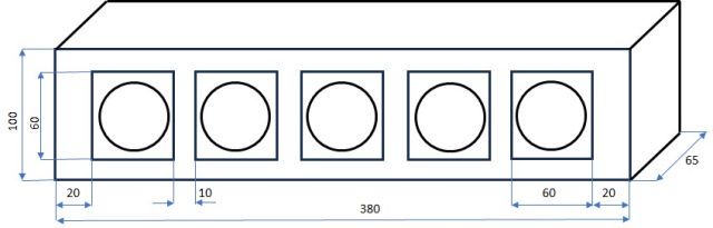
Fig. 1 Geometric dimensions of a linear directional source
The directional line source uses FR58-8 (8Ω) loudspeakers from Visaton. The view of the loudspeaker from the side of the diaphragm and the magnet is shown in Fig. 2. The loudspeaker is mounted with four screws. The coil terminals are located on the magnet side.
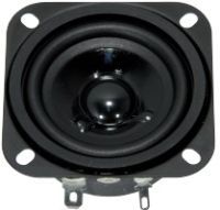
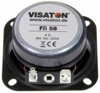
Fig. 2 View of the loudspeaker used in the directional source
The geometric parameters of the loudspeaker are shown in Fig. 3.
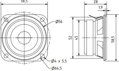
Fig. 3 Geometric parameters of the FR 58 loudspeaker
As you can see, the width of the loudspeaker is approximately 60 mm and it determines the total width of the line source. Spacing of 10 mm between loudspeakers was necessary due to the mechanical stability of the source structure.
The value of the rated power is sufficient for measurement purposes (amplifiers with an output power of up to 5W were used). An important parameter is the speaker impedance. It is available in two versions: 4 Ω or 8 Ω. The directional sources use loudspeakers with an impedance of 4 Ω and power amplifiers adapted to drive loudspeakers with such an impedance.
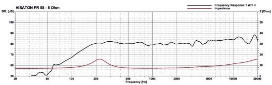
Fig. 4 Transfer and impedance characteristics of the FR 58-8 loudspeaker (manufacturer's data)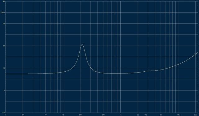
Fig. 5 Impedance characteristics of the FR 58-8 loudspeaker as a function of frequency without housing
The frequency characteristics and the impedance versus frequency provided by the manufacturer are shown in Fig. 4. As can be seen in the characteristics of the impedance module, there is a characteristic increase in its value around 220 Hz. This should be taken into account when designing the loudspeaker casing and selecting the control system working with the loudspeaker.
In order to verify the impedance characteristics given in the manufacturer's data sheet (Fig. 4), an additional measurement of its module as a function of frequency was performed. Fig. 5 shows the impedance waveform of the FR 58-8 loudspeaker measured using the Clio system. As you can see, it coincides with the waveform shown in Fig. 4. The directional characteristics of the FR 58-8 loudspeaker for frequencies from 500 Hz to 8000 Hz are shown in Fig. 6. Here you can see the feature of the dynamic transducer mentioned in the introduction, which is that, together with as the frequency increases, it becomes more and more directional and it is possible to construct a directional source based solely on this property of the transducer.
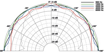
Fig. 6 Directional characteristics of the FR 58 loudspeaker
The design of the line source was made in accordance with Fig. 1. The FR 58-8 loudspeakers were mounted in separate damped chambers. The view of the base of the linear matrix before its finishing is shown in Fig. 7. The mechanical structure of the housing consists of three layers glued together. This structure ensures good housing stiffness and minimizes possible resonances.
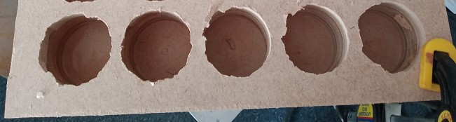
Fig. 7 Mechanical structure intended to embed loudspeakers
After the chambers were finished, they were properly damped using damping material before placing the loudspeakers (Fig. 8). As you can see from the photo, the speakers are mounted with four screws after inserting them into the damped chambers.
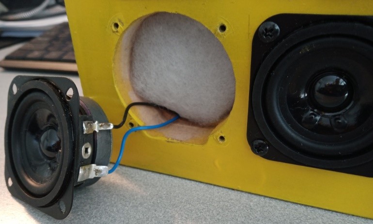
Fig. 8 View of the interior of the chamber with damping material
After installing the loudspeakers, verification measurements were performed to check whether the source casing improved the characteristics of the loudspeaker impedance module as a function of frequency. Measurements were made using the Clio system. Fig. 9 shows the course of the impedance of the selected FR 58-8 loudspeaker as a function of frequency after it is placed in an individual housing in the form of a hollow and damped chamber of the directional sound source. You can clearly see the influence of the casing on the characteristics. The resonance occurring in the characteristics is much smaller than that measured and shown in Fig. 5.
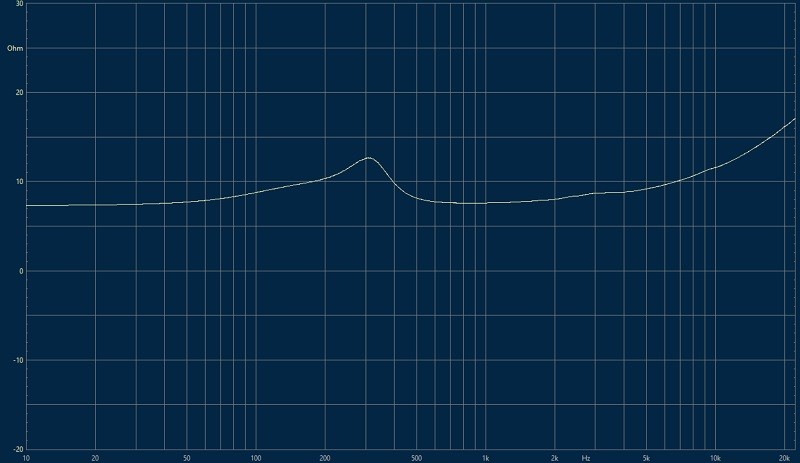
Fig. 9 Impedance characteristics of the FR 58-8 loudspeaker as a function of frequency after placing it in the line source housing
The view of the finished line array with five dynamic loudspeakers installed is shown in Fig. 10.
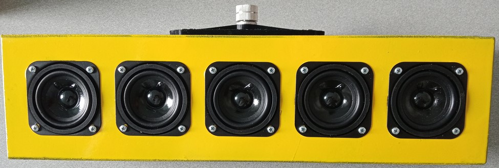
Fig. 10 Linear matrix – front view
The view of the linear matrix from the side of the mounting adapted to be screwed to the stand enabling the measurement of its parameters is shown in Fig. 11.
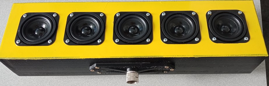
Fig. 11 Linear matrix - view from the side of mounting to the stand
Fig. 12 shows a holder in the form of a nut that facilitates mounting the source on a stand intended for measuring the parameters of a linear array. In terms of its geometric parameters, the holder has been adapted to use standard photographic tripods. With the exception of the mounting nut, the handle structure was designed and then printed using a 3D printer.
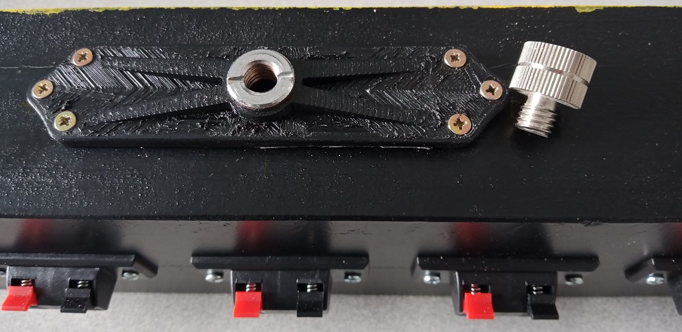
Fig. 12 Fixing the linear matrix (the photo nut lying next to the mounting structure is visible)
Fig. 13 shows the stand holder and the loudspeaker sockets used (independent for each loudspeaker placed in the directional line source).
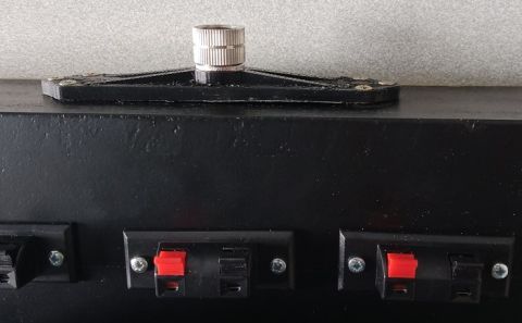
Fig. 13 Independent loudspeaker sockets for each loudspeaker
The internal speaker wiring takes into account the fact that proper connection of the power amplifier outputs to the speaker terminals should ensure that the speakers are connected in phase. So inside the housing, each speaker output is connected to the same (color-coded) speaker terminal.
Power amplifiers
In addition to the transducer (dynamic loudspeaker), a power amplifier is a very important element in a directional sound source. It should be taken into account that, depending on the number of transducers built into the source, an important parameter may be the effectiveness (or efficiency) of the amplifier, achieved even at the expense of parameters such as its non-linear distortions. The LTK5128 series integrated circuits are used as power amplifiers in the linear matrix system. These are monophonic electro-acoustic amplifiers with an output power of up to 5W. They enable operation in two modes: class D or class AB. A special pin (marked with the MODE symbol) is intended for switching between operating classes.
The amplifier system is characterized by low electromagnetic interference both when operating in class D and AB. Of course, in the case of class AB they are smaller. The supply voltage range is from 2.5V to 5.5V. The efficiency of a class D amplifier exceeds 90%. The power amplifier circuit is based on an interesting solution in which the output does not include a low-pass filter, usually required in class D amplifiers. This approach reduces the cost of the amplifier and its dimensions, which allows it to also be used in mobile devices. One of the important sources of non-linear distortions is the phenomenon of limiting (cutting) the amplitude of the output signal when its maximum permissible value is exceeded. The amplifier uses dynamic range control technology to reduce distortion caused by clipping of the signal waveform when the signal amplitude is too high.
The block diagram of the system in accordance with the manufacturer's catalog card is shown in Fig. 15.
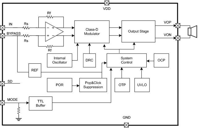
Fig. 15 Block diagram of the LTK5128 system
Fig. 16 shows the schematic diagram of the amplifier recommended by the manufacturer. This arrangement is used in a linear sound source.
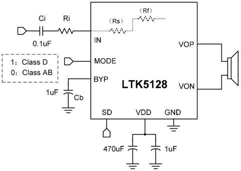
Fig. 16 Recommended application of the amplifier
To avoid problems related to power supply interference during measurements, a battery (Power Bank) was used as a power supply. This was possible even when twenty-five power amplifiers were powered at the same time, because the amplifiers operated in class D and their efficiency was over 90%. One battery charge was enough for several measurement cycles. Fig. 24 shows a fragment of a breadboard with power amplifiers intended to control the line source loudspeakers.
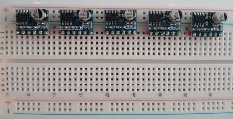
Fig. 24 Breadboard with power amplifiers prepared for installation
Fig. 25 shows an enlarged view of two power amplifiers driving the loudspeakers of a directional line source.
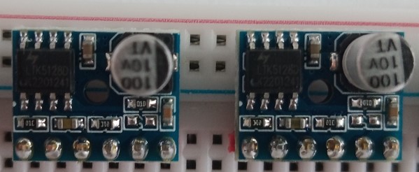
Fig. 25 Two power amplifiers designed to control the speakers of a line source
Fig. 26 shows a breadboard with power amplifiers that control the operation of a directional linear sound source assembled using sections of wires. The number of amplifiers is equal to the number of speakers of the linear sound source. The connections on the breadboard are made in such a way that individual channels (speakers) can be quickly disconnected from the signal source and the effect of deactivating a selected component of the source on its parameters can be checked.
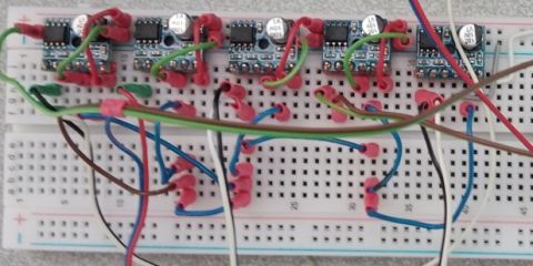
Fig. 26 Board with mounted power amplifiers controlling the line source speakers
Fig. 27 shows the block diagram of the line source. As you can see, it consists of five speakers and five power amplifiers driving them.
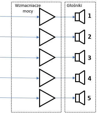
Fig. 27 Block diagram of a line source composed of five transducers
Fig. 28 shows a view of the complete executive system of a directional line source consistent with the block diagram shown in Fig. 27. As mentioned, the use of a battery eliminates any problems related to interference from the power supply system. Of course, in the system presented in Fig. 28, other components can be used, e.g. a voltage stabilizer or a laboratory power supply.
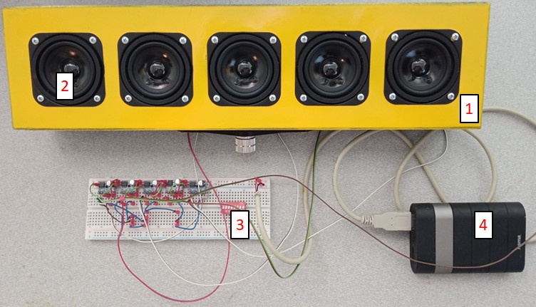
Fig. 28 Line source (1) with dynamic speakers (2), amplifier board (3) and power supply (4)
Fig. 29 shows the line source from the side of the speaker connector sockets.
Fig. 29 Directional line source – actuator visible from the side of the loudspeaker sockets
Appropriate socket colors ensure that the correct phase parameters of the line source components are maintained by maintaining the correct way of connecting the power amplifier outputs to the loudspeakers.
Digital delay circuit
Another element of the directional line source is the delay circuit. PT239X series CMOS digital echo/delay processors developed by Princeton Technology Corp. are used in each channel. The official datasheets released by Princeton Technology are vague and many of the internal functions of the chips are not explained, giving rise to mods and out-of-the-box solutions. Therefore, the information presented below comes from various sources, primarily from sources available on the Internet. The schematic diagram of the system developed for use as a directional source delay system is shown in Fig. 33.
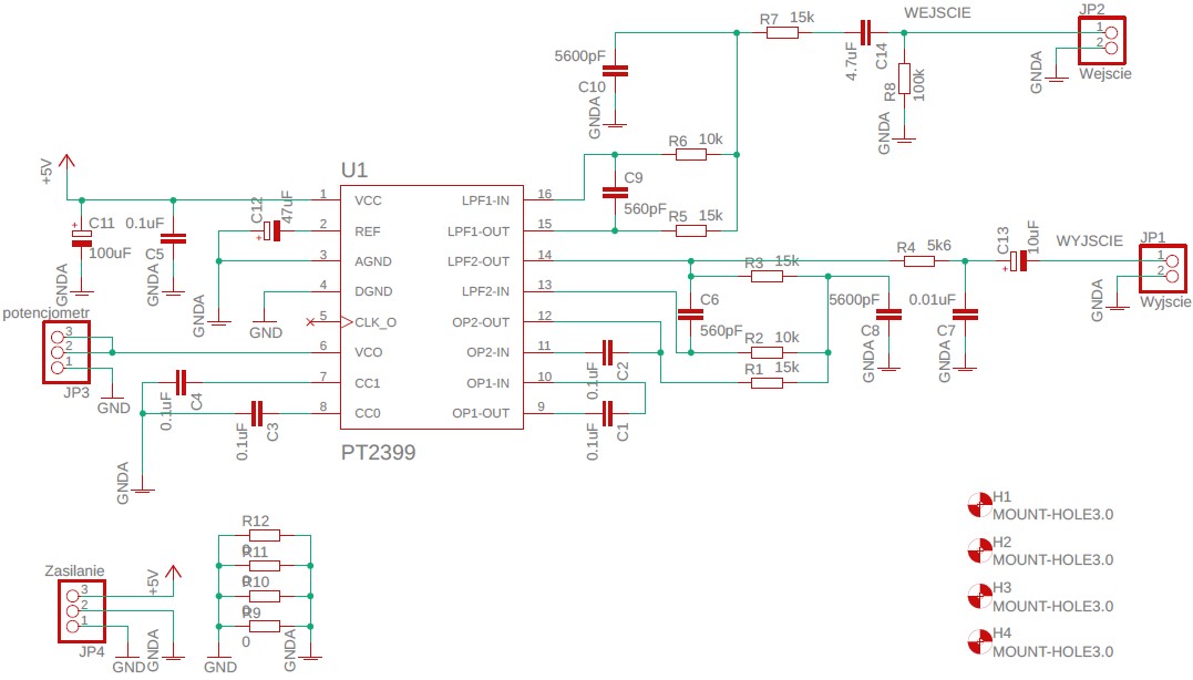
Fig. 33 Schematic diagram of the acoustic signal delay system
As you can see, this is a delay version, not an echo effect, which can also be designed using the PT2399 chip. It must be clearly emphasized that this is very important, because due to the principle of operation of the directional source, we are only interested in the signal delay effect.
The view of the printed circuit board implementing the delay function of the analog signal is shown in Fig. 35. It shows the two most important components: a digital integrated circuit that performs the function of a delay line and a multi-turn potentiometer for adjusting the delay value. A multi-turn potentiometer is used here due to the accuracy of delay adjustment.
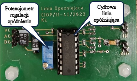
Fig. 35 Board implementing the analog signal delay function
The board containing five delay circuits, i.e. the number of transducers in the linear directional source system, is shown in Fig. 36.
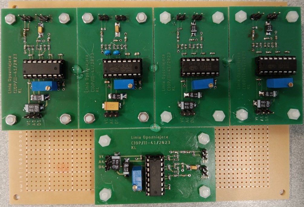
Fig. 36 Base board with five delay boards
The delay systems are made in two versions. They differ in potentiometers used to adjust the delay value. In the first version, these are the mentioned multi-turn potentiometers shown in Fig. 35 and Fig. 36. In the second version, these are digital potentiometers. Fig. 37 shows a schematic diagram of a digital potentiometer whose resistance can be changed using the SPI serial interface.
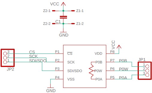
Fig. 37 Schematic diagram of a digital potentiometer with three pins
Fig. 38 shows a printed circuit board designed in accordance with the diagram shown in Fig. 37. This board has been adapted to be mounted in the base plate shown in Fig. 34. In this way, the traditional potentiometer can be replaced with a digitally controlled potentiometer without the need to modify the base plate. printed circuit board.
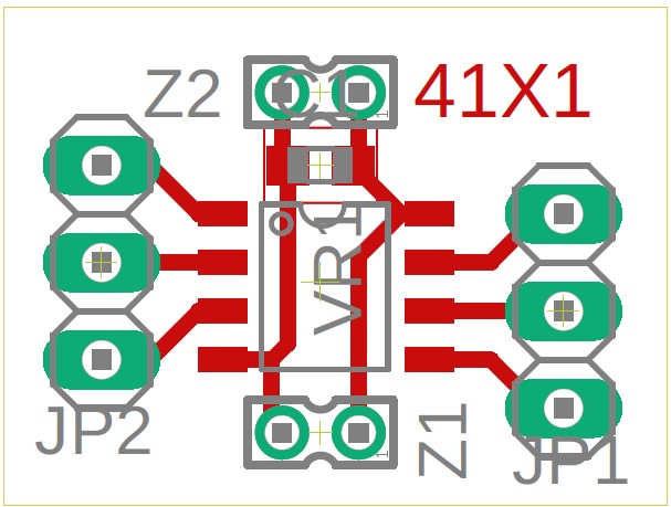
Fig. 38 Digital potentiometer printed circuit board with three pins
Fig. 39 shows a schematic diagram of a digital potentiometer whose resistance, similarly to the potentiometer in Fig. 37, can be changed using the SPI serial interface. Unlike the potentiometer in Fig. 37, it is a potentiometer with only two terminals (so-called rheostat). However, from the point of view of the delay system, this is not a limitation.

Fig. 39 Schematic diagram of a digital potentiometer with two pins (rheostat)
Fig. 40 shows a printed circuit board designed in accordance with the diagram shown in Fig. 39. This board has been adapted to be mounted in the base board shown in Fig. 34.
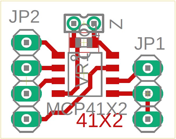
Fig. 40 Printed circuit board of a digital potentiometer with two pins (rheostat)
The block diagram of a line source with delay systems and power amplifiers driving the loudspeakers is shown in Fig. 41.
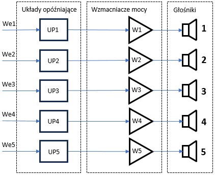
Fig. 41 Block diagram of a line source with delay circuits
Fig. 42 shows a view of the base board from Fig. 36 after its wiring to match the block diagram shown in Fig. 41 (excluding amplifiers and transducers).
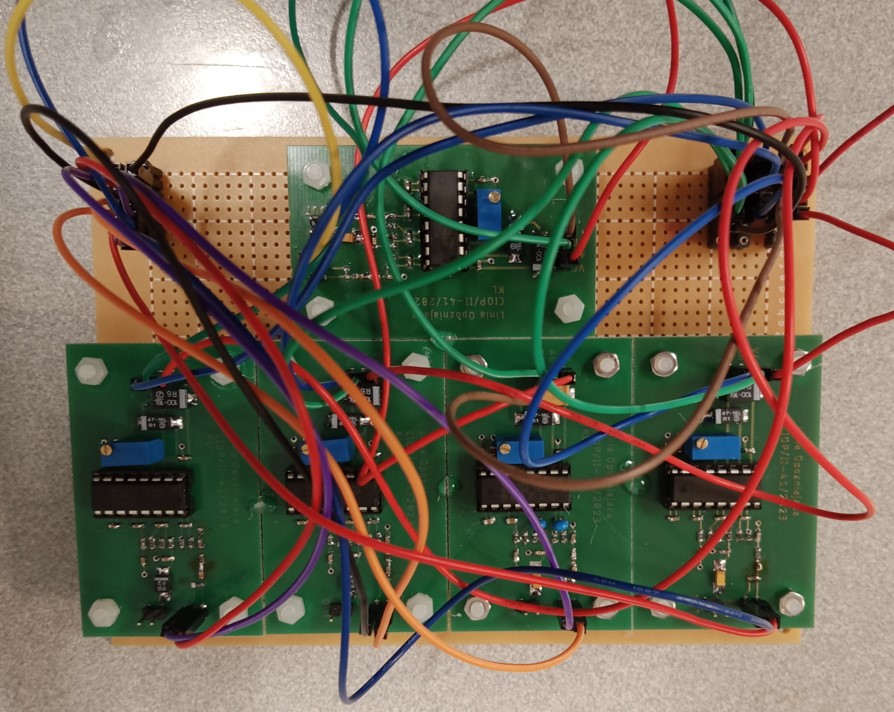
Fig. 42 Wired base board from Fig. 36
Fig. 43 shows boards with digital delay circuits (board on the right) and power amplifiers (part of the board on the left).
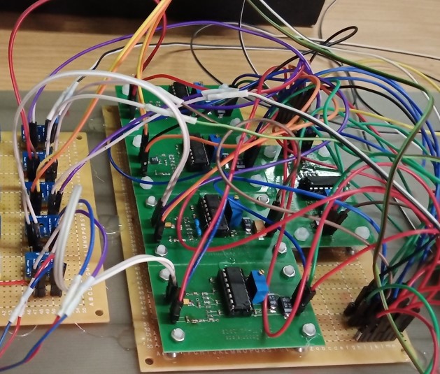
Fig. 43 Board with digital delay circuits connected to power amplifiers driving loudspeakers
The components described above in the context of a line source are the same in the case of the loudspeaker matrix in the first version. In the case of the second version of the speaker matrix, the difference is that the speakers built into it have their own power amplifiers with gain controls.
Rozplanowanie przetworników oraz podstawowe wymiary geometryczne matrycy głośnikowej w wersji drugiej pokazane są na Rys. 44. Jak widać matryca ma 355 mm wysokości na 355 mm szerokości na 65 mm głębokości. Odległości pomiędzy głośnikami wynoszą 5 mm, zaś odległość skrajnych głośników od krawędzi bocznych, górnej i dolnej matrycy wynosi 20 mm.
Speaker matrix – version 1
The arrangement of the transducers and the basic geometric dimensions of the loudspeaker matrix in the second version are shown in Fig. 44. As you can see, the matrix is 355 mm high by 355 mm wide by 65 mm deep. The distances between the speakers are 5 mm, and the distance of the extreme speakers from the side, top and bottom edges of the matrix is 20 mm.
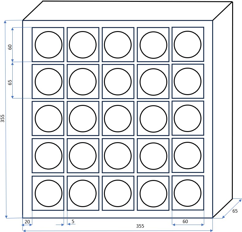
Fig. 44 Geometric parameters of the loudspeaker matrix version 1
The matrix is composed of 25 transducers, the same as those used in the directional line source, and has a square shape. The same power amplifiers are also used here. Similarly to the line source, the design is based on a multi-layer structure with milled holes. The view of the matrix at the stage of construction of the supporting structure is shown in Fig. 45 and Fig. 46.
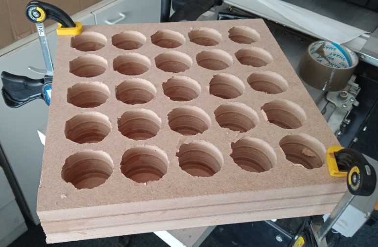
Fig. 45 View of the supporting structure of the loudspeaker array at the processing stage
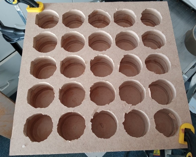
Fig. 46 View of the supporting structure of the loudspeaker array at the processing stage
Fig. 47 shows an enlarged fragment of the supporting structure. It shows in detail the three-layer structure in which chambers are milled for placing damping material and mounting loudspeakers.
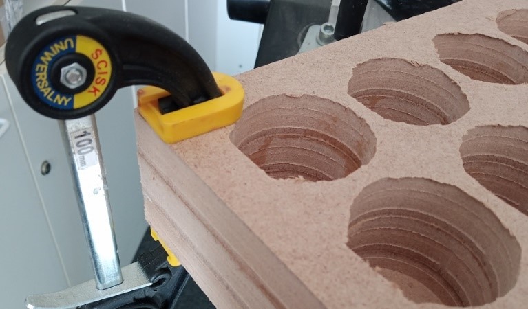
Fig. 47 Close-up view of the supporting structure
Fig. 48 shows the finished matrix after dampening the chambers and installing the loudspeakers in them.
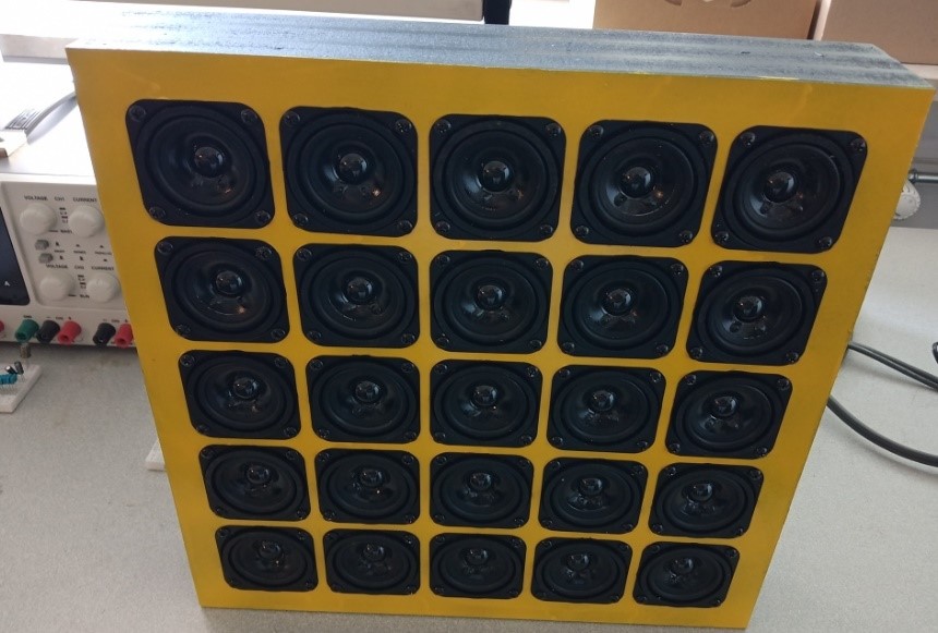
Fig. 48 Front view of the assembled loudspeaker array
Fig. 49 shows the rear view of the loudspeaker matrix in the first version.
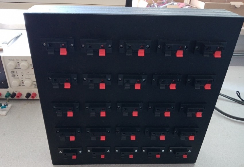
Fig. 49 View of the assembled loudspeaker matrix from the back, from the side of the loudspeaker sockets
Similarly to the line source, the loudspeaker sockets are internally wired in such a way that the appropriate loudspeaker outputs are connected to the appropriate (colored) terminals of these sockets. This makes it easier to connect loudspeakers with power amplifiers in such a way that there will be no unintentional phase reversal of the radiated acoustic wave.
Speaker matrix – version 2
The geometric dimensions of the matrix are shown in Fig. 50. Unlike the matrix in the first version, the geometric dimensions were imposed not only by the dimensions of the transducers, but by the dimensions of the factory housings in which they were built.
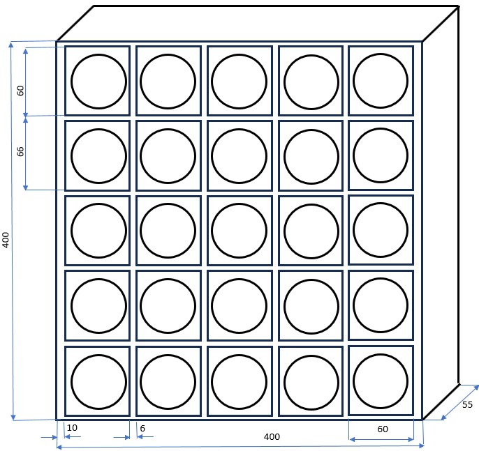
Fig. 50 Basic geometric dimensions of the loudspeaker matrix version 2
Unlike the matrix in version 1, the matrix is based on miniature loudspeakers with built-in amplifiers, which were selected as part of the first stage of the research task. These are ready-to-use loudspeakers in housings. Their view is shown in Fig. 51.
Similarly to the directional loudspeaker array version 1, taking into account the geometry of the acoustic beam shaping system, the matrix sound source with controlled directional characteristics takes the form of a square array of loudspeakers distributed evenly on the plane. Due to the expected applications, such a source should be composed of loudspeakers with the smallest possible geometric dimensions (which translates into a small size of the matrix source and its easier installation) and a possibly wide frequency response band (this will result in a better reproduction of real sound signals, including speech). According to the results of the market analysis conducted in the first stage of the research task, LOGIC LS-09 loudspeakers were selected as loudspeakers. LOGIC LS-09 loudspeakers are compact sets placed in closed housings with dimensions of 55 mm (W) x 70 mm (W) x 50 mm (D). According to the manufacturer, the effective power of each speaker is 3W RMS, and the frequency response is 200÷20000 Hz. The view of the speakers is shown in Fig. 51.
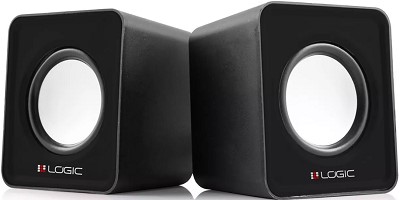
Fig. 51 View of loudspeakers in housings constituting elements of the loudspeaker matrix
LOGIC LS-09 loudspeakers were used primarily to study the influence of the number of loudspeakers and their relative location on the parameters of the matrix in narrow signal frequency ranges. Their housings have regular shapes and enable simple assembly of matrices of various degrees of complexity. As mentioned, the dimensions of the housing are close to a cube (73x73x70 mm). The interior of the loudspeaker housings after dismantling the cover is shown in Fig. 52. As you can see, inside the housing there is a board with a power amplifier placed vertically in relation to the loudspeaker. Unfortunately, the housing is not soundproofed. Each set consists of two loudspeakers in housings. This is due to the fact that it is designed to reproduce sound in a stereo system. The housings are connected by a signal cable that transmits the signal of one of the channels to the loudspeaker in the housing without an amplifier circuit.
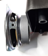
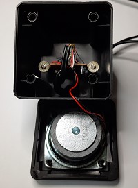
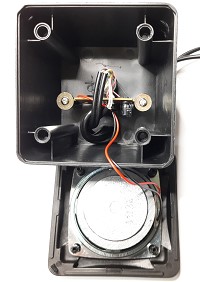
Fig. 52. The interior of the LOGIC LS-09 loudspeakers and similar available models
The electronic system, i.e. a power amplifier with gain control, is placed in one housing (Fig. 53). The second one contains only the loudspeaker. The photo on the left shows the printed circuit board from the side of the electronic components, the middle photo shows the board from the side of the gain control potentiometer, and the photo on the right shows the view of the board mounted inside the loudspeaker housing after removing the loudspeaker.
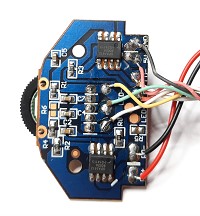
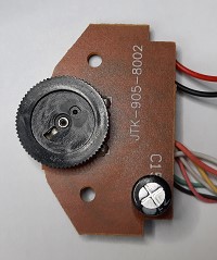
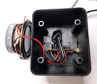
Fig. 53. Electronic circuits (amplifier and gain controller) located inside the loudspeaker housing
Due to the fact that the matrix contains both loudspeakers in housings with an amplifier and without an amplifier board, measurements were made to check whether such a connection would be correct from the point of view of the matrix parameters. One of the measurements was the measurement of the impedance as a function of the frequency of the loudspeaker after removing it from the housing and after placing it in the housing with and without the amplifier board. Fig. 54 shows the impedance of the Esperanza loudspeaker as a function of frequency. The measurement using the Clio system was performed for the speaker removed from the factory housing.
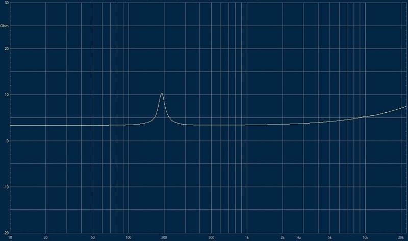
Fig. 54 Impedance waveform of the Esperanza loudspeaker without the housing
Fig. 55 shows the impedance of the Esperanza loudspeaker as a function of the frequency of the loudspeaker placed in the factory housing. In the case of a housing without a board with an amplifier circuit, the waveform of the loudspeaker impedance module after placing it in the housing does not change and is the same as that shown in Fig. 54. The resonance frequency is approximately 190 Hz. In the case of a loudspeaker placed in a housing with an amplifier board, the impedance module changes only slightly, as shown in Fig. 55. The resonance frequency decreases to 180 Hz.
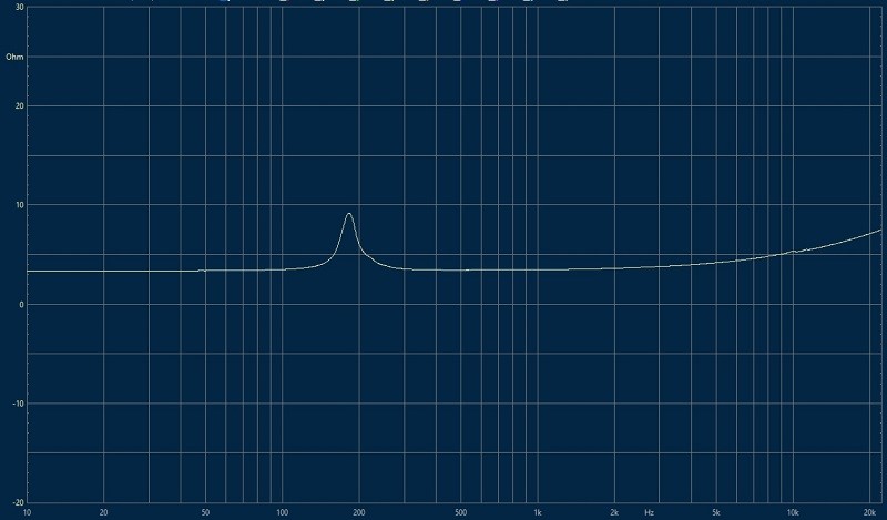
Fig. 55 Impedance waveform of the Esperanza loudspeaker placed in the factory housing
A comparison of the waveforms shown in Fig. 54 and Fig. 55 therefore shows that the loudspeaker housing only slightly affects the frequency response of the loudspeaker impedance. As in the case of the directional line source and matrix in the first version, the design of the supporting structure took into account the unfavorable phenomenon of spatial aliasing and the loudspeakers in the housings were placed as close to each other as possible. The original casings were used in the source design.
In the first stage of the research task, it was envisaged that the matrix could be built by connecting the housings, e.g. using double-sided adhesive tape. An example visualization of a matrix composed of twelve loudspeakers is shown in Fig. 56. When examining various forms of implementing the matrix design, the possibility of using original signal amplification stages is taken into account (circuits shown on the printed circuit board on the left in Fig. 53).
")
")
")
")
")
")
")